Presonus Firepod FP10 DC Coupling Mod
Don’t attempt this mod unless you are comfortable with the risks!
Ever since Motu released Volta a couple of years ago, I’ve been obsessed with exploring the possibilities of directly outputting control voltages from DAWs and other software tools (Expert Sleeper’s ‘Silent Way‘ and Max are my current faves). Rock solid timing, DAW automation sync, whats not to love? I didn’t like the idea of buying an 828 just to add DC capabilities to my rig, as I had already invested some cash into an 8 channel Presonus setup and was quite happy with it.
As it turns out, the Presonus Firepod (“FP-10” post copyright injunction) audio interface’s DAC is capable of outputting DC control voltages. Unfortunately, Presonus opted to put some blocking capacitors at the end of the signal path, removing any DC present in the output. These caps might clean up a bit of offset by design, but the only noise I’ve noticed since bypassing them is a slight rustling sound when I move the volume pots on the front panel, which isn’t a problem for me. Here is a fully reversible way to disable them and control your synth with your Firepod or FP-10:
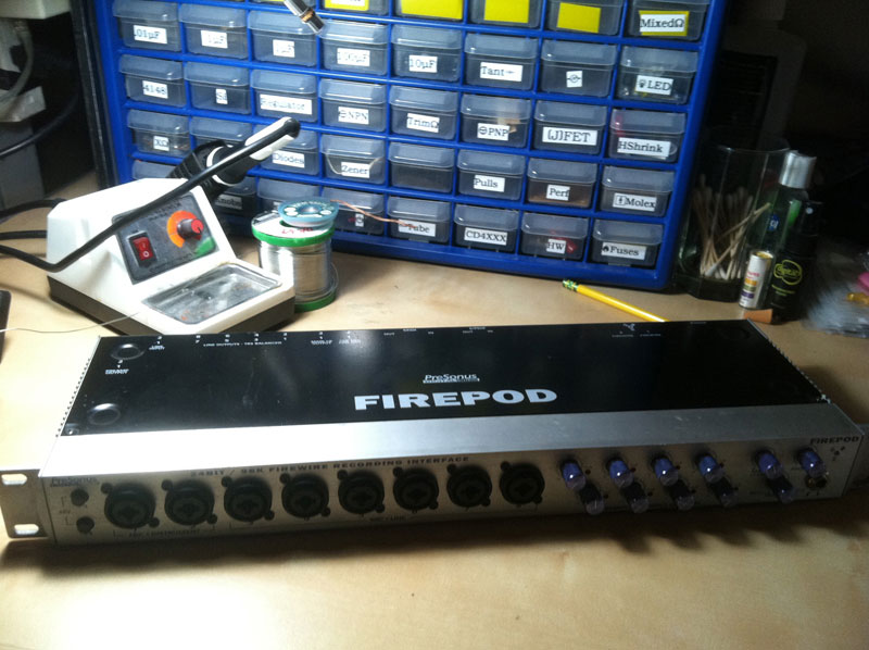 |
Step 1: Disconnect Firepod from power supply. |
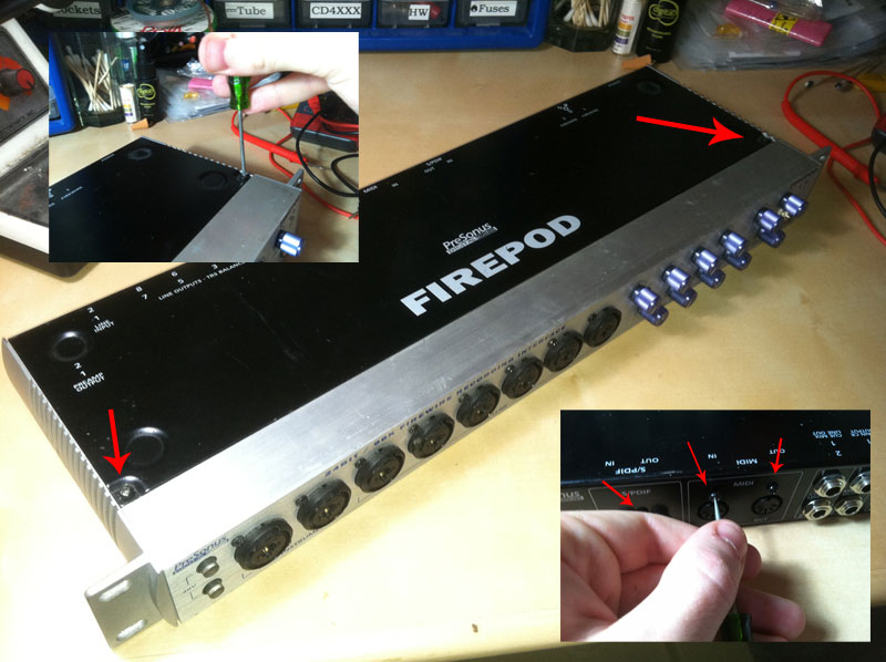 |
Step 2: Remove chassis screws. There are 2 on top, 3 on the back, and 3 on the bottom. |
 |
Step 3: Pull the front assemby forward to expose the molex connectors. |
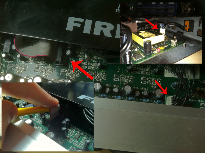 |
Step 4: Carefully disconnect the 3 ribbon connectors to separate pcb from chassis. You will have to go in through the right side where the rack ear was to remove one of them. |
 |
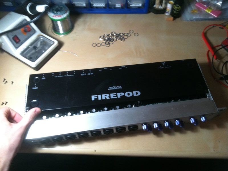
Step 5: Pull the front assembly from the chassis. If you meet resistance, you could try removing the entire 1/4″ jack assembly by removing all of the nuts and washers from the back. |
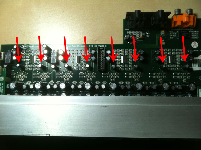 |
Step 3: Locate the eight decoupling capacitors situated above the DAC chips. They should be labeled 10uf. |
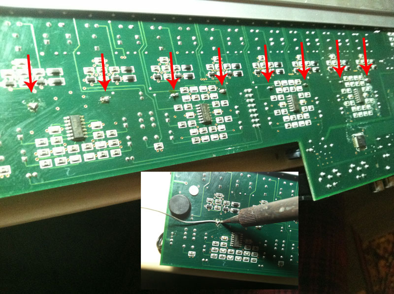 |
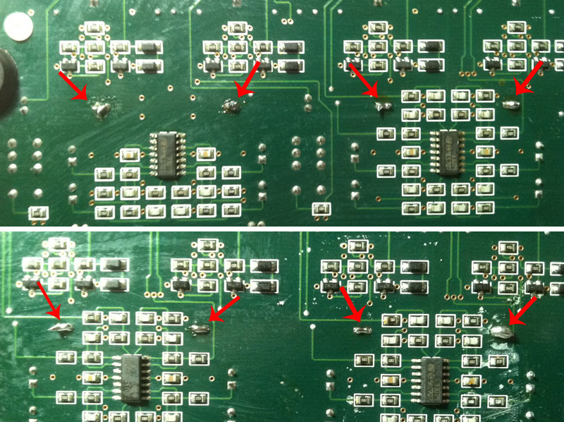
Step 4: Flip the PCB and solder a small bridge between the two leads of each capactitor (eight jumpers). This makes for a completely reversible mod- just use some desoldering braid to remove the jumpers if you are unhappy with the results and want to revert to a DC blocking state. |
 |
Step 5: Reverse dissasembly. You should be good to go. I tested mine by sending a constant ‘1’ signal to the outputs in Max/MSP and testing the outputs with a scope. A multimiter should work just fine. |
When you test your interface after making any modifications be sure to slowly ramp up the volume to protect your monitors in the case there are any weird voltages leaking through the outputs.